Iranian Classification Society Rules

< Previous | Contents | Next >
Section 4 Control, Monitoring and Safety System
401. General
1. A local reading pressure gauge is to be fitted between the stop valve and the connection to shore at each bunker pipe.
2. Pressure gauges are to be fitted to gas pump discharge lines and to the bunkering lines.
3. A bilge well in each tank room surrounding an independent liquid gas storage tank is to be pro- vided with both a level indicator and a temperature sensor. Alarm is to be given at high level in bilge well. Low temperature indication is to lead to automatic closing of main tank valve.
402. Gas tank monitoring
1. Gas tanks are to be monitored and protected against overfilling as required in Ch.5, 1302. and
1303. of the Rules.
2. Each tank is to be monitored with at least one local indicating instrument for pressure and remote pressure indication at the control position. The pressure indicators are to be clearly marked with the highest and lowest pressure permitted in the tank. In addition, high-pressure alarm, and if vacuum protection is required, low pressure alarm is to be provided on the bridge. The alarms are to be activated before the set pressures of the safety valves are reached.
403. Gas compressor monitoring
Gas compressors are to be fitted with audible and visual alarms both on the bridge and in the en- gine-room. As a minimum, the alarms are to be in relation to low gas input pressure, low gas out- put pressure, high gas output pressure and compressor operation.
404. Gas engine monitoring
1. Additional to the instrumentation provided in accordance with Pt.5 of the Rules for Steel Ships, in- dicators are to be fitted on the navigation bridge, the engine control room and the maneuvering platform for:
(1) Operation of the engine in case of gas-only engines; or
(2) Operation and mode of operation of the engine in the case of dual fuel engines.
2. Auxiliary systems where gas may leak directly into the system medium (lubricating oil, cooling wa- ter) are to be equipped with appropriate gas extraction measures fitted directly after the outlet from the engine in order to prevent gas dispersion. The gas extracted from auxiliary systems media is to be vented to a safe location in the open.
405. Gas detection
1. Permanently installed gas detectors are to be fitted in the tank room, in all ducts around gas pipes, in machinery spaces of the ESD-protected type, compressor rooms and other enclosed spaces con- taining gas piping or other gas equipment without ducting. In each ESD-protected machinery space, two independent gas detector systems are to be required.
2. The number of detectors in each space is to be considered taking size, layout and ventilation of the space into account.
3. The detection equipment is to be located where gas may accumulate and/or in the ventilation outlets. Gas dispersal analysis or a physical smoke test is to be used to find the best arrangement.
![]()
4. An audible and visible alarm is to be activated before the vapour concentration reaches 20% of the lower explosion limit (LEL). For ventilated ducts around gas pipes in the machinery spaces contain- ing gas-fuelled engines, the alarm limit can be set to 30% LEL. The protective system is to be ac- tivated at a LEL of 40%.
5. Audible and visible alarms from the gas detection equipment are to be located on the bridge and in the engine control room.
6. Gas detection for gas pipe ducts and machinery spaces containing gas-fuelled engines is to be con- tinuous without delay.
506. Safety functions of gas supply systems
1. Each gas storage tank is to be provided with a tank valve capable of being remote operated and is to be located as close to the tank outlet as possible.
2. The main gas supply line to each engine or set of engines is to be equipped with a manually op- erated stop valve and an automatically operated "master gas fuel valve" coupled in series or a combined manually and automatically operated valve. The valves are to be situated in the part of the piping that is outside machinery space containing gas-fuelled engines, and placed as near as possible to the installation for heating the gas, if fitted. The master gas-fuel valve is automatically
to cut off the gas supply as given in be operable from a reasonable number
Table 3.1. And, the automatic master gas fuel valve is to of places in the machinery space containing gas-fuelled en-
gines, from a suitable location outside the space and from the bridge.
3. Each gas consuming equipment is to be provided with a set of "double block and bleed" valves.
These valves are to be arranged as outlined in Fig. 3.1 or Fig. 3.2 so that when automatic shut-
down is initiated as given in Table 3.1, this will cause the two
gas fuel valves that are in series
to close automatically and the ventilation valve to open automatically and:
(1) Two of these valves are to be in series in the gas fuel pipe to the gas consuming equipment.
The third valve is to be in a pipe that vents to a safe location in the open air that portion of the gas fuel piping that is between the two valves in series. The function of one of the valves in series and the ventilation valve can be incorporated into one valve body, so arranged that the flow to the gas utilization unit will be blocked and the ventilation opened.
(2) The two block valves are to be of the fail-to-close type, while the ventilation valve should be fail-to- open.
(3) The double block and bleed valves are also to be used for normal stop of the engine.
4. In cases where the master gas fuel valve is automatically shutdown, the complete gas supply branch downstream of the double block and bleed valve is to be ventilated, if reverse flow from the en- gine to the pipe must be assumed.
5. There is to be one manually operated shutdown valve in the gas supply line to each engine up- stream of the double block and bleed valves to assure safe isolation during maintenance on the engine.
6. For one-engine installations and multi-engine installations, where a separate master valve is provided for each engine, the master gas fuel valve and the double block and bleed valve functions can be combined. (Examples for the high-pressure system are shown in Fig. 3.1 and 3.2.)
7. The total loss of ventilation in a machinery space for a single fuelled gas system is, additionally to what is given in Table 3.1, to lead to one of the following actions:
(1) For a gas electric propulsion system with more than one machinery space: Another engine is to start. When the second engine is connected to bus-bar, the first engine is to be shutdown automatically.
(2) For a direct propulsion system with more than one machinery space: The engine in the room
with defect ventilation is to be manually shutdown, if at least 40% propulsion power is still available after such a shutdown.
If only one machinery space for gas-fuelled engines is fitted and ventilation in one of the enclosed ducts around the gas pipes is lost, the master gas fuel and double block and bleed valves in that supply line are to be closed automatically provided the other gas supply unit is ready to deliver.
![]()

Figure 3.1. Alternative supply valve arrangements for high-pressure installations (single engine or separate master valve arrangement)
![]()
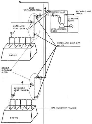
Figure 3.2 Alternative supply valve arrangements for high-pressure installations (multi-engine installation)
8. If the gas supply is shut off due to activation of an automatic valve, the gas supply is not to be opened until the reason for the disconnection is ascertained and the necessary precautions taken. A readily visible notice giving instruction to this effect is to be placed at the operating station for the shut-off valves in the gas supply lines.
9. If a gas leak leading to a gas supply shutdown occurs, the gas fuel supply is not to be operated until the leak has been found and dealt with. Instructions to this effect are to be placed in a prominent position in the machinery space.
10. A signboard is to be permanently fitted in the machinery space containing gas-fuelled engines stat- ing that heavy lifting, implying dan- ger of damage to the gas pipes are not to be done when the engine(s) is running on gas.
![]()
![]()
Table 3.1 Monitoring of gas supply system to engines
Parameter | Alarm | Automatic shutdown of main tank valve | Automatic shutdown of gas supply to machinery space containing gas-fuelled engines | Remarks |
Gas detection in tank room above 20% LEL | X | |||
Gas detection on two detectors 1) in tank room above 40% LEL | X | X | ||
Fire detection in tank room | X | X | ||
Bilge well high level tank room | X | |||
Bilge well low temperature in tank room | X | X | ||
Gas detection in duct between tank and machinery space containing gas-fuelled engines above 20% LEL | X | |||
Gas detection on two detectors 1)in duct between tank and machinery space containing gas-fuelled engines above 40% LEL | X | X 2) | ||
Gas detection in compressor room above 20% LEL | X | |||
Gas detection on two detectors 1) in compressor room above 40% LEL | X | X 2) | ||
Gas detection in duct inside machinery space containing gas- fuelled engines above 30% LEL | X | If double pipe fitted in machinery space containing gas-fuelled engines | ||
Gas detection on two detectors 1) in duct inside machinery space containing gas-fuelled engines above 40% LEL | X | X 3) | If double pipe fitted in machinery space containing gas-fuelled engines | |
Gas detection in machinery space containing gas-fuelled engines above 20% LEL | X | Gas detection only required for ESD protected machinery space |
![]()
Table 3.1 Monitoring of gas supply system to engines (continued)
Gas detection on two detectors 1) in machinery space containing gas-fuelled engines above 40% LEL | X | X | Gas detection only required for ESD protected machinery space containing gas-fuelled engines. It is also to disconnect non certified safe electrical equipment in machinery space containing gas-fuelled engines | |
Loss of ventilation in duct between tank and machinery space containing gas-fuelled engines 6) | X | X 2) 4) | ||
Loss of ventilation in duct inside machinery space containing gas-fuelled engines 6) | X | X 3) 4) | If double pipe fitted in machinery space containing gas-fuelled engines | |
Loss of ventilation in machinery space containing gas-fuelled engines | X | X | ESD protected machinery space containing gas-fuelled engines only | |
Fire detection in machinery space containing gas-fuelled engines | X | X | ||
Abnormal gas pressure in gas supply pipe | X | X 4) | ||
Failure of valve control actuating medium | X | X 5) | Time delayed as found necessary | |
Automatic shutdown of engine (engine failure) | X | X 5) | ||
Emergency shutdown of engine manually released | X | X | ||
Note : 1) Two independent gas detectors located close to each other are required for redundancy reasons. If the gas detector is of self monitoring type the installation of a single gas detector can be permitted. 2) If the tank is supplying gas to more than one engine and the different supply pipes are completely separated and fitted in separate ducts and with the master valves fitted outside of the duct, only the master valve on the supply pipe leading into the duct where gas or loss of ventilation is detected is to close. 3) If the gas is supplied to more than one engine and the different supply pipes are completely separated and fitted in separate ducts and with the master valves fitted outside of the duct and outside of the machinery space containing gas-fuelled engines, only the master valve on the supply pipe leading into the duct where gas or loss of ventilation is detected is to close. 4) This parameter is not to lead to shutdown of gas supply for single fuel gas engines, only for dual fuel engines. 5) Only double block and bleed valves to close. 6) If the duct is protected by inert gas (See 107. 1) then loss of inert gas overpressure is to lead to the same actions as given in this table. | ||||
![]()